
So you want to design a synth, or at least understand how all those DIY modules you have been building actually work, but don’t know where to start... then this is the post for you! We will go over the basic principles of electronics and some of the first building blocks to add to your arsenal of analysis and design tools. This post will presume that you understand voltage in the context of modular synthesis (CV and audio-rate voltage) but not in the context of electrical engineering. Understanding some simple mathematics (Algebra I level) and a familiarity with the metric prefix system will also be useful - brush up on those here and here (respectively). The end of the post will also assume that you have a basic understanding of a filter in modular synthesis, but not in the context of analog electronics.
For you, voltage mostly just means a signal that takes on a value that may change with time - or stay the same. In any case, you just send that numeric value over a patch cable to another module which does something with the voltage and outputs a response signal. Conceptually, voltage to you is no different than automation in a digital audio workstation or the waveform of an audiofile - albeit a bit more arcane in its ethereal-yet-physical embodiment as electricity. Well if it’s arcane, then its time for you to become a wizard!
Voltage, Current, Resistance, and the Mississippi River
So what is voltage, really? You know it’s got something to do with electricity... As a starting point, let’s look at the fact that we commonly refer to signal in our patches as “flowing” from point A to point B - and in turn we see that electricity flows from point A to point B. What we mean when we say this is that electrons - like, a lot of electrons - are flowing from point A to point B. This flow of electrons defines what we call a current. But wait - that’s not voltage!
You’re right! Current and voltage are two very different things. Current represents how many electrons are flowing past a point over a given duration of time, while voltage represents how strong that current is. You might be thinking, “but aren’t those the same thing? For instance, doesn’t the amount of water flowing by determine the pressure of the flow?" Well, you are keen to make a comparison to water, and are correct in thinking that the amount of water flowing by is important in determining the strength of the flow, but it is not the only factor - they are not the same thing!
The analogy to a stream of water is useful - to a point - in helping us understand current and voltage, so let’s explore it further. First though, we have to give this analogy a cool name...the Hydraulic Analogy is what is typically used. We will make repeated analogies to water, but it is important to remember that these analogies are never perfectly isomorphic. Instead, they should always, only, be considered mnemonic tools to help build intuition in select circumstances for how electricity works.
Imagine a river - perhaps the Mississippi, I hear it’s nice this time of year - on a serene, slow day. You probably wouldn’t mind going for a swim in it, were it a little bit cleaner. It certainly wouldn’t sweep you away, and you would have no trouble treading water. The pressure (voltage) that the water is exerting on you is really not that great. You are swimming happily. The current though is quite massive - if we were to draw a line from one bank of the river to the other and measure the volume of water that went past in one second it would be quite a lot!
Now imagine that same volume of water coming out of your bathroom every second. For maximum effect, imagine it to be the middle of the night after your super put off coming by to fix that pesky shower head once again. You would not be happy, nor would your synths be happy, and CERTAINLY not your synthkitty, as you and all your belongings (and likely your whole apartment building) are pulverized in a Pynchonesque deluge of... sewer water. The current, or volume of water flowing by per second, is the same in both cases, but the pressure of the water (voltage) is entirely different. So what changed?
The channel through which the water is flowing became greatly constricted. The narrower the passage, the more fierce the flow of water. Think back to children playing with hoses. When the thumb is away from the mouth of the hose, water comes out at a leisurely pace, but cover it up and it becomes a geyser-like jet of water for exerting dominance over playground peers.
In summary...- The pressure of this flow is equivalent to voltage, measured in.... you guessed it, Volts!
- The volume of this flow per unit of time is equivalent to the current, or number of electrons flowing by per second, measured in Coulombs/second, also known as Amperes or amps for short. (Note a “coulomb” is like the word “dozen”. It’s just a specific, very large number instead of 12. 1 C/s = 1 A)
- Finally, the narrowness of the passage through which the water flows is equivalent to a new concept which we call resistance and will measure in Ohms (Ω).
| Voltage | Current | Resistance |
|---|---|---|
| Volts (V) | Amps (A; or Coulumbs/Sec) | Ohms (Ω) |
| Electrical Potential | Current Rate, i.e. electrons/second | Opposition to Current |
| Water Pressure | Water Flow Rate | Narrowness of water channel |
Ohm's Law
In the last examples, you may have noticed that we kept the current flow constant and only changed the resistance. When the resistance increased, the voltage increased, and when the resistance decreased, the voltage decreased! Similarly, let’s think about a shower head: the diameter of the holes stays the same at all times, so we can’t change the resistance. But we can change the current! As we turn our knob, we send more and more water through our shower head, and the pressure of the water gets greater and greater! Just like when we kept current constant, if we keep resistance constant, but increase current, voltage increases. Alternatively, when we decrease current but keep resistance constant, voltage decreases.
Resistors are electrical components that have different resistances. They are like lengths of pipe tubing for water to flow through, with different resistances corresponding to different diameters of pipe. The lower the resistance, the wider the pipe! Greater resistance means narrower pipes.

Schematic symbol for a resistor
These relationships between current, resistance, and voltage can be beautifully captured by the extraordinarily elegant mathematical equation known as Ohm’s Law (by the way that photo of Izzy in their bio was taking at a club called Ohm. Pretty cool if you ask me!):
If my curent is 2mA (2 milliAmps, or 2/1000 Amps, or .002 Amps) and my resistance is 4kOhms (4 kiloOhms, or 4,000 Ohms) then my voltage is:
Likewise, if my voltage is 4V and my current is 2 Amps, then my resistance must be 2Ohms!
Since \(V=IR\), we can say that:
\begin{align} I = \frac{V}{R} \text{, and } R = \frac{V}{I} \end{align}Remember, Ohms Law expects all units to be in Volts, Amps, and Ohms. In the context of modular synths, we will frequently see units in milliAmps (mA) or kiloOhms (kOhms). If you are going to use Ohm’s Law, remember to do the following:
Convert currents measured in milliAmps to Amps by dividing the mA value by 1000 (since there are 1000 milliAmps in 1Amp) .
Convert resistances measured in kiloOhms to Ohms by multiplying the kOhm value by 1000 (since there are 1kiloOhm for every 1000 Ohms).
Finally, keep in mind that whenever you know two quantities, you can always find the third!
Electric Potential, Voltage Drops and Voltage Sources: Oceans In the Sky
So, now let’s talk about schematics. A schematic is a way of representing how different electrical components are connected to each other. In the case of our water analogy, it would be a description of how pipes, valves, pumps, pinwheels, and vacuums are connected together to control the flow of water. A line on a schematic indicates a trace, wire, or net, all of which we can conceptualize as a path for current to take with 0 resistance. “Trace” and “wire” both refer to the physical manifestation on a circuit board, while “net” typically refers to the abstract representation in a schematic.
Where does current come from, and where does it go to?
Current will always flow from places in the circuit with higher electric potential to places with lower electric potential.
What is electric potential?
Electric potential is like the energy stored in a stretched rubber band, or the energy stored in a a reservoir of water stored above the ground. If we release the rubber band, it will move towards a lower energy state by contracting; if we connect a pipe to the tower, the water will move towards a lower energy state by flowing to ground. In terms of electricity, if we create a path from a voltage source to ground (which has 0 potential), current will flow! If we placed a water wheel in the path of the water current, we could use our flow to do work, like spinning a pin wheel! We can use our electricity to do work as well by placing a load in the current path!
What is “ground” (GND) in the electrical context?
Simply put, it is defined as a place in the circuit with 0 electric potential - an equilibirum state. As such, on all schematics, ground is a point that is a common destination (or sink) for all current coming from positive voltage sources, and a source of current for negative voltages.
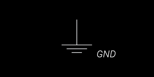
Schematic symbol for ground

Adapted from Wikipedia, Hydraulic Pressure
What actually creates our “electrical tension” or “electrical pressure”, like stretching the rubber band or raising the water up?
If we are using batteries, then it would come from a difference of ion concentrations in two chemical solutions - this is known as electrochemistry! If a synth is plugged into the wall, then ultimately the electrical potential energy would come from the position of a magnet in relation to a coil in a generator somewhere at a power facility on the electric grid.
What are voltage drops?
If you imagine a schematic as a bunch of water towers and pipes, GND is like a reservoir on the literal ground to which all water eventually flows, while voltage sources are the water towers suspended in the air. The higher the tower, the higher the electric potential! Voltage is a measurement of the difference in electric potential between any two points in the circuit. Typically, we measure the voltage, or difference in electric potential, between a given node in the circuit and GND, however we can measure the voltage difference, or “voltage drop,” between any two arbitrary points! This is like comparing how much energy is stored in an extremely taught rubber band to a moderately taut rubber band, or the energy stored in a 100ft water toware to a 50ft water tower. The voltage drop between any two points can always be calculated by simply finding the resistance between the two points, finding the current flowing between two points, and multiplying them together - this can get tricky when there are multiple paths from one point to another, but we will cross that bridge (or bridges!) when we get to it.
What is a voltage source?
A constant voltage source is an entity that can vary its current output in order to keep its voltage drop to GND constant. In other words, if a voltage source outputs V volts, when you measure the resistance R from the voltage source to ground and the current I flowing from the voltage source to ground, then the product IR will always be equal to V! Since the voltage source can’t vary the resistance of its path to ground, it achieves this by varying its current output.
Consider the two schematics below. In the first, since the resistance to ground is 100kOhms and the voltage source is +12v, the current output must be \(I = \frac{12V}{100000 Ω} = .12 mA\). In the second exmaple, with R = 200kOhms, the voltage source will output \(I = \frac{12V}{200000 Ω} = .06 mA\).


What if we want to analyze circuits with more than just one element though? We will need to learn a few new concepts to do so - fortunately, they are quite intuitive, and you can use simple analogies to remember them.
Kirschoff's Current Law
The first is Kirschoff’s Current Law, or KCL. The law is stated as follows:
The sum of the currents flowing into a node must be equal to the sum of the currents flowing out of that node.
This is just like a fork in a river! The same amount of water that approaches a fork in a river must leave the fork, even if it has multiple exit paths! If we add up the current leaving the fork on each of the two paths, it must be equal to the current that entered the fork. Whenever you see a fork in a current’s path, you can think of the fork as peeling off two separate substreams of current that add up to the original current.
Sometimes you might see this written with fancy notation using the Greek later Σ (pronounced “sigma”). In mathematics, Sigma is like a simple command that says “take all the instances of whatever comes after me, and add them up.”
$$I_{1}=I_{2} + I_{3}$$

Kirschoff's Voltage Law
Next, let’s talk about Kirschoff’s Voltage Law, or KVL. The formal way statement is as follows:
The voltage drop around any closed loop in a circuit is 0 Volts.
Conceptually though, you can think of it a little more clearly and intuitively than this! If I measure the voltage between two points A and B and write it down, I will find that same voltage by doing the following:
Choose any path from the point A to point B.
Add an arbitrary number of points along the path, breaking it up into smaller segments
Find the voltage drop from for each individual segment (i.e. from one point to the next point in the path)
Add up all these adjacent voltage drops, and it will be equal to the originally found voltage!
NB: The voltage drop along any two points on a wire is always 0v since the resistance along a wire is 0Ω!
Consider a glacier on top of a mountain that all of a sudden completely melts. No matter what path any given current of water takes down the mountain, in the end, the drop in altitude (voltage drop) will always be the same! I could examine any individual path, break it down into smaller steps, and add up the drop in altitude for each step, and in the end, I would ultimately end up with the total drop in altitude from the glacier’s original height to the bottom of the mountain. We can use this to start understanding schematics with more than one component!

Series Resistors
Let’s look at this schematic:

We say that two components (or even whole sections of a circuit) are in "in series" when they are connected sequentially, providing a single path for current to flow.
We know that the input voltage \(V_{in}\) is coming from a constant voltage source, and the voltage drop from the source to ground is equal to Vin. But what is the total resistance \(R\) from node A to ground? How much current \(I\) is leaving our voltage source and traveling through the resistors?
First, we know that the voltage drop from A to GND must be Vin since we have a constant voltage source. By Kirschoff’s Voltage Law (KVL), we know that the voltage drop \(V_{1}\) from A to B plus the voltage drop \(V_{2}\) from B to GND must be equal to Vin, so by KVL, we can write:
$$ V_{in} = V_{1}+V_{2} $$What is V1, the voltage drop from A to B? Well, by Ohm’s Law, we know that the voltage drop across R1 must be the current I across R1 times the resistance. The same logic applies to R2. Since there is only a single path for the current, by KCL, we know the same current I must pass through both resistors. As such, we can write the following two equations:
Now, we can subsitute these values for V1 and V2 into our original equation:
\begin{align} V_{in} & = I\times R_{1} + I\times R_{2} \\ & = I\times(R_{1}+R_{2}) \end{align}Since I is the current flowing between A and GND, we can see that the resistance between the two points must just be R1+R2!
Whenever two resistors are connected in series, the total resistance they present to a path of current attempting to flow through them consecutively is just equal to the sum of their resistances, \(R_{1}+R_{2}\)!
Parallel Resistors
Next, let’s consider this schematic, as well as a water tower depiction on the right:
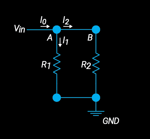
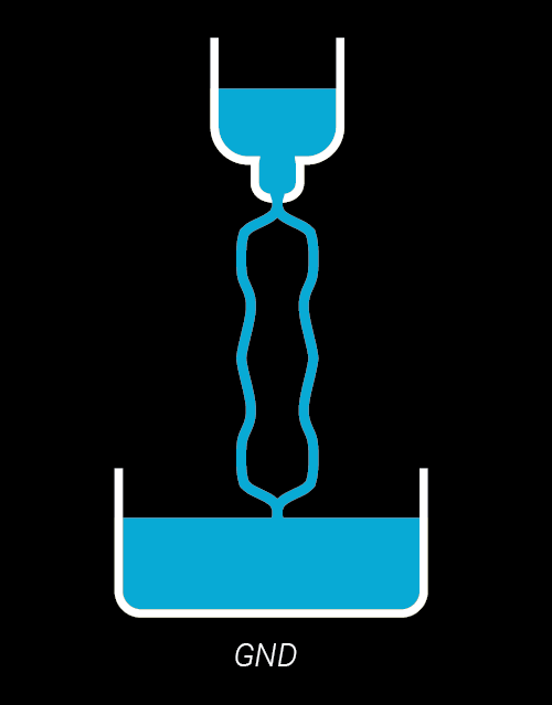
We say that two components (or even whole sections of a circuit) are connected "in parallel" when they provide two independent current paths from a single source node to a single destination node.
First let’s think about it in terms of current. There’s some amount of current flowing into node A from the power supply. Note that the same amount of current that goes into A has to come out of A, just like a fork in the river. This means that the sum of the current I1 and the current I2 must be equal to I0.
\begin{align} I_{in} & = I_{out} \\ I_{0} & = I_{1}+I_{2} \end{align}Next, let’s consider the voltage. Since we have a a constant voltage source, we know the voltage drop from A to GND will be equal to Vin no matter what. The voltage source will output the precise amount of current I0 such that whatever the resistance R from A to GND is, the product of I0R will be equal to Vin.
However, we also know that the voltage drop from B to GND will be equal to Vin since there is no voltage drop from A to B, because the resistance between these two nodes is 0Ω! From there, we can figure out that the current flowing along each of our two paths by realizing that the voltage drop across both R1 and R2 must be Vin:
\begin{align} I_{1} & = \frac{V_{in}}{R_{1}} \\ \\ I_{2} & = \frac{V_{in}}{R_{2}} \\ \\ I_{0} & = I_{1} + I_{2} \\ \\ & = \frac{V_{in}}{R_{1}} + \frac{V_{in}}{R_{2}} \\ \\ & = V_{in} \times (\frac{1}{R_{1}}+\frac{1}{R_{2}}) \\ \\ & = V_{in}\times (\frac{R_{2}}{R_{1}R_{2}}+\frac{R_{1}}{R_{1}R_{2}})\\ \\ I_{0} & = V_{in}\times \frac{R_{1}+R_{2}}{R_{1}R_{2}} \end{align}By Ohm's Law though, we know that the resistance R from A to GND is just Vin divided by I0, so we can apply some simple algebra to that last equation to solve for the resistance!
\begin{align} R & = \frac{V_{in}}{I_{0}}\\ \\ & = \frac{R_{1}R_{2}}{R_{1}+R_{2}} \\ \\ & = \frac{1}{\frac{1}{R_{1}}+\frac{1}{R_{2}}} \end{align}>So, whenever we have two resistors in parallel, meaning they provide two independent paths from one node to another node, as in the above schematic, then we can say that the total resistance they provide is actually equal to the quantity \(\frac{R_{1}R_{2}}{R_{1}+R_{2}}\) or alternatively the quantity \(\frac{1}{\frac{1}{R_{1}}+\frac{1}{R_{2}}}\)
Voltage Divider
So, let’s finally put all this analysis we’ve been doing to use, by learning about your first modular building block: the voltage divider. The voltage divider is an incredibly useful tool for scaling voltages down. Suppose you have a point in your circuit which you know needs to be +2.5v, but you only have a +5v source? How do you do this? A voltage divider might be the right answer! Maybe you have a point which you know needs to be 1/5th of an incoming voltage, regardless of the input voltage? A voltage divider might be the right answer again! Depending on the application, another solution like a voltage reference, voltage regulator, or operational amplifier might be a better choice, but in many simple cases, a voltage divider will do the trick!

Our goal is to find \(V_{out}\), based off of our known input voltage \(V_{in}\) and the value of our two resistors, \(R_{1}\) and \(R_{2}\). Notice that \(V_{out}\) is the same thing as the voltage drop from B to GND. Let’s analyze this to figure it out!
First, we know that the voltage drop from A to GND is equal to our input voltage, Vin. However, let’s divide the path between these two points into smaller segments - the first segment will be from node A to node B. The second path will be from B to GND.
Using Kirschoff's Voltage Law, we can write the following:
$$ V_{in}=V_{1}+V_{out} $$We don't know how much current is leaving our voltage source, but we do know that the current must run through both R1 and R2 since there is no other path for it take. Let's call that current \( I \). Notice though that R1 and R2 are just sereis resistors going to GND, meaning the total resistance from A to GND is just \(R_{1}+R_{2}\). As such, we know that \(V_{in}= I\times(R_{1}+R_{2})\). We can now solve for I using algebra:
$$ I = \frac{V_{in}}{R_{1}+R_{2}}$$Now that we know I, we can use Ohm's Law to find the voltage drop across R2:
\begin{align} V_{out} & = I\times R_{2}\\ \\ & = \frac{V_{in}}{R_{1}+R_{2}}\times R_{2}\\ \\ & = V_{in}\times\frac{R_{2}}{R_{1}+R_{2}} \end{align}The voltage gain (denoted \(A_{v}\)) of a signal is defined to be the ratio of the output voltage to the input voltage, so for a voltage divider, we can write the following gain formula:
$$ A_{v} = \frac{V_{out}}{V_{in}}=\frac{R_{2}}{R_{1}+R_{2}} $$As you can see, the numerator of the fraction will always be less than the denominator, so we will always scale our voltage down by some amount. By carefully choosing our resistor values, we can achieve a desired scaling factor! Let’s do some examples to get a better feeling for this in action.
Suppose \(V_{in} = +10V\) and \(R_{1}=R_{2}=100\Omega\). What will \(V_{out}\) be? Let's just plug into our voltage divider equation to find out!
\begin{align} V_{out} & = V_{in}\times \frac{R_{2}}{R_{1}+R_{2}} \\ \\ & = 10V \times \frac{100\Omega}{100\Omega + 100\Omega} \\ \\ & = 10V \times \frac {100\Omega}{200\Omega} = 10V \times \frac{1}{2} \\ \\ & = 5V \end{align}Notice that no matter what values we choose for R1 and R2, if they are equal, the voltage divider ratio will always end up being 1/2!
Now, suppose you have an input voltage that you want to scale down. Perhaps your input voltage is +10v, and you want to output +3.3v. How can you do this? First, figure out the ratio of your output to input: \(\frac{V_{out}}{V_{in}} = \frac{3.3V}{10V} = \frac{1}{3}\). In other words, you want to divide your voltage down by a factor of 3. How can you achieve this? Well, since \(\frac{V_{out}}{V_{in}} = \frac{R_{2}}{R_{1}+R_{2}}\), we can set the voltage divider fraction equal to \(\frac{1}{3}\) and use algebra to solve for the relationship between R1 and R2!
\begin{align} \frac{1}{3} & = \frac{R_{2}}{R_{1}+R_{2}} \\ R_{1} + R_{2} & = 3\times R_{2}\\ R_{1} & = 2\times R_{2} \end{align}Let's say that you pick \(R_{2}=100\Omega\). Then you should make \(R_{1} = 2\times R_{2} = 2\times 100\Omega = 200\Omega\).
Suppose you have a sine wave with an amplitude of 5v, i.e. it goes from +5v to -5v, or in other words is 10v peak-to-peak. Perhaps you want it to end up with a 1v amplitude. Well, then we want \(\frac{V_{out}}{V_{in}} = \frac{1}{5}\), so we can find our resistor ratio using the same method as before: \begin{align} \frac{1}{5} & = \frac{R_{2}}{R_{1}+R_{2}} \\ R_{1} + R_{2} & = 5\times R_{2}\\ R_{1} & = 4\times R_{2} \end{align}
Noticing a pattern? Whenever you want your voltage divider output to be \(V_{out}=\frac{1}{n}\times V_{in}\), then the first resistor R1 should always be \(R_{1}=(n-1)\times R_{2}\).
Finally, let's observe that our analysis depended on the current through both resistors being the same. If we want to use Vout for anything though, we would need to tap the signal at B and send it off somewhere else for use! However, in that case, due to Kirschoff's Current Law, some current would be peeled off, and the current through R1 and R2 would no longer be the same! Solution: After tapping the output signal at B, send it through a very large resistor before passing it off to your destination in order to make the amount of current peeled off is as minimal as possible. Alternatively, you can buffer the output signal using an op-amp or a common-emitter transistor, where "buffer" means "copying" a voltage but providing an alternate source of current for your load. More on op-amps and transistors in coming posts!
Now that you have a basic idea of some of the fundamental principles of resistors, let's turn to a new component: the capacitor.
Capacitors
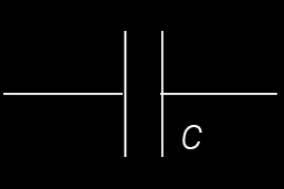
Schematic symbol for a capacitor
For many people (myself included) capacitors are much harder to conceptualize than resistors. When discussing resistors so far, we did not really care at all what the input signal looked like: it could be a static voltage, or it could be an oscillating signal, and in either case, the resistors behave the same - they just impeded the flow of current through them. Capacitors on the other hand change the way they behave depending on what the signal passing through them is and even how long that signal has been passing through it! This is the first, most important thing to remember with capacitors.
There are two primary conceptual models for capacitors:
Energy storage devices that can charge up and discharge
“Frequency-dependent resistors” (i.e. components who resist the flow of current depending on the frequency of the input signal)
For the purpose of the budding synthesis engineer, the second is the more useful model, so we will focus on that. Just like resistors have a resistance R associated with them, every capacitor has a value associated with it called its capacitance, C, measured in Farads. 1 Farad though is considered extremely large. In the context of synthesizer designs, you will virtually never see a capacitor with a capacitance greater than 50uF, or 50 microFarads (.000050 Farads). Typically, you will see capacitors in the pico-, nano-, and microFarad ranges, with values between 1pF (1 picoFarad, or .000000000001 Farads) and 22uF (22 microFarads, or .000022 Farads).
For our purposes, our main interest in the capacitance of a capacitor will be to determine how much the capacitor impedes signals depending on their frequency. Based off of this capacitance, for a signal at a given frequency f, we can determine a new quantity called reactance, denoted by XC. Reactance XC is measured in Ohms, and is just the capacitor’s impedance to a signal at a given frequency! For now, you can think of impedance and resistance as being more or less the same thing... For a capacitor with capacitance \(C\), the formula for its reactance \(X_{c}\) at a given frequency \(f\) is given by:
$$ X_{c} = \frac{1}{2\pi fC} $$Let’s do a few examples with a 100 nF capacitor. For a signal at 100Hz, reactance of the capacitor will be: $$ X_{c} = \frac{1}{2\pi \times 1nF \times 100Hz} = \frac{1}{2\pi \times 1\times 10^{-7}F\times 100Hz} = 15,915\Omega $$ What if the signal is at 1kHZ? $$ X_{c} = \frac{1}{2\pi \times 1nF \times 1kHz} = \frac{1}{2\pi \times 1\times 10^{-7}F\times 1000Hz} = 1,591\Omega $$ And 10kHZ? $$ X_{c} = \frac{1}{2\pi \times 1nF \times 10kHz} = \frac{1}{2\pi \times 1\times 10^{-7}F\times 10,000Hz} = 159\Omega $$ Let's jump to 1MHz, and notice that the capacitor's reactance goes down to virtually nothing: $$ X_{c} = \frac{1}{2\pi \times 1nF \times 1MHz} = \frac{1}{2\pi \times 1\times 10^{-7}F\times 1\times 10^{6}Hz} = 1\Omega $$

As you can see, for a given capacitor, if frequency goes up, reactance will go down! To summarise: the greater the frequency, the lower the reactance. Lower frequency means greater reactance! Similarly, if we hold frequency of our input signal constant, but replace our capacitor with one of greater capacitance, reactance will go down, while replacing it with a lower capacitance cap will increase reactance.
Finally, let’s consider what happens when we apply a static voltage to a capacitor, as in the diagram below. A static voltage can be thought of as a signal with a frequency equal to 0Hz. So what would the reactance be? We can’t divide by 0, so how do we calculate it? Well, we know that the lower the frequency, the greater the reactance - as we get to smaller and smaller and smaller frequencies, our reactance just keeps getting higher and higher and higher. We can then say that as the frequency approaches 0Hz, the reactance approaches infinite Ohms. As such, we simply say that the reactance at 0Hz is infinite. This means that capacitors essentially block all static voltages from passing any current through them!
So, to summarize: to static (DC) and low frequency signals, the capacitor looks like an open circuit (no path for current), at midrange frequencies, a capacitor looks like a resistor, and at high frequencies, a capacitor looks like a short circuit (i.e. a wire with no resistance). As the capacitor gets bigger, the boundary frequency for each of these regions gets shifted lower and lower (i.e. bigger caps can pass lower frequencies).

Capacitive Voltage Dividers: Passive Highpass and Lowpass Filters
Let’s exploit frequency-dependent capacitance property of capacitors to build some simple filters!
Consider a voltage divider with the first resistor replaced with a capacitor with C = 100nF, while the second resistor going to ground has a resistance of 1kOhms.

Now, consider sending a sine wave through the filter, oscillating at frequency f. What does the circuit look like from the perspective of the signal? Well, the resistor looks the same. But the capacitor can be replaced with an impedance equal to the capacitor’s reactance!

Now, this is just a voltage divider, as we saw above! Initially, you might expect that the gain of the signal would be equal to \(\frac{R}{X_{c}+R}\), our standard voltage divider formula, but it’s not quite right… when dealing with impedance (opposition to flow of AC current), the impedance Z of a resistor and a capacitor in series is not their sum, but rather the square root of the sum of their squares: \(Z = \sqrt{R^{2}+X_{c}^{2}}\) - it’s close, but not quite equal in value to their sum. We will just replace the series resistance \(R+X_{c}\) in the denominator of our voltage divider formula with the series impedance \(Z\). The gain \(A_{v}=\frac{V_{out}}{V_{in}}\) of our capacitive voltage divider will then be as follows: $$ A_{v} = \frac{V_{out}}{V_{in}} = \frac{R}{Z} = \frac{R}{\sqrt{R^{2}+X_{c}^2}} $$ Now let's pick some real values, and see what happens! As stated above, let's let \(R = 1k\Omega\) and \( C = 100nF\). What happens to a 10kHz sine wave that has an amplitude of 5V? First we need to calculate the reactance, then we need to calculate the series impedance, and then we will plug into our voltage divider equation to find the gain.
\begin{align} X_{c} & = \frac{1}{2\pi\times f\times C} = \frac{1}{2\pi\times 10,000Hz\times 1\times 10^{-7}F} = 159\Omega \\ \\ Z & = \sqrt{X_{c}^2+R^{2}} = \sqrt{(159\Omega)^{2}+(1,000\Omega)^{2}} = 1012\Omega\\ \\ A_{v} & = \frac{R}{Z} = \frac{1000\Omega}{1012\Omega} = .98 \approx 0dB \end{align}So, we essentially just have unity gain for a sine wave at 10kHz! This should make perfect sense, since at such a high frequency, the reactance was so low that the capacitor was almost just like a bare wire allowing the signal to pass right through.
Let's see what happens when we send a 1kHz sine wave through: \begin{align} X_{c} & = 1,591\Omega\\ \\ Z & = 1,879\Omega\\ \\ A_{v} & = .53 \approx -5.5dB \end{align}
Since our input sine wave had an amplitude of 5v, our output sine wave will have an amplitude of \(A_{v}\times V_{in} = 0.53\times 5V \approx 2.5V\).
What about an input sine wave at 100Hz?
\begin{align} X_{c} & = 15,915\Omega\\ \\ Z & = 15,946\Omega\\ \\ A_{v} & = .06 \approx -24.5dB \end{align}What if we try to send a constant DC voltage through our divider? Well, a constant voltage is just like a signal with a 0Hz frequency, though we can't divide by zero when we attempt to calculate reactance, we do know that as frequency approaches zero, reactance approaches \(\infty\), so we can essentially just replace the capacitor with an open break in the circuit, not allowing any signal to pass through. Alternatively, we could see that as reactance approach infinity, so too will impedance, and as such, the gain will be 0.
So, let' summarize our results from this experiment:
$$C=100nF, R=1k\Omega $$| Frequency f(Hz) | Reactance Xc (Ohms) | Series Impedance Z (Ohms) | Gain Av |
| 0 | ∞ | ∞ | 0 |
| 100 | 15,915 | 15,946 | .06 |
| 1,000 | 1,591 | 1,879 | .53 |
| 10,000 | 159 | 1,012 | .98 |
So as our frequency increases, our gain increases. As our frequency decreases, our gain decreases. This is just a highpass filter! It is known as a passive highpass filter, because it does not require any external power source - you merely pass your signal through the network, and voila! In the future we will look at active filters, i.e. filters that use integrated circuits which require a power supply to run.
Your next question will likely be: what is the cutoff frequency of this filter? Well, typically, we define the cutoff frequency to be the frequency at which gain of a sine wave is exactly -3dB, or in other words the gain ratio is exactly \(A_{v} = \frac{1}{\sqrt{2}}\). Let’s use some algebra to solve for this frequency!
\begin{align} A_{v} & =\frac{R}{Z} \\ \\ \frac{1}{\sqrt{2}} & = \frac{R}{Z} \\ \\ Z & = R\times \sqrt{2} \\ \\ \sqrt{X_{c}^{2} + R^{2}}& =R \times \sqrt{2} \\ \\ \sqrt{X_{c}^{2} + R^{2}}^{2} & = (R\times \sqrt{2})^{2} \\ \\ X_{c}^{2} + R^{2} & = 2\times R^{2} \\ \\ X_{c}^{2} & = R^{2} \\ \\ \sqrt{X_{c}^{2}} & =\sqrt{ R^{2}} \\ \\ X_{c } &=R \\ \\ \frac{1}{2\pi\times f\times C} & = R\\ \\ f & = \frac{1}{2\pi\times R\times C} \end{align}Now that we have the general form for the cutoff frequency of a passive highpass filter, all we need to do is substitute in our capacitor and resistor values to find the cutoff frequency for this particular filter!
\begin{align} C & = 100nF, R = 1k\Omega\\ \\ f & = \frac{1}{2\pi\times 1\times 10^{-7}Hz\times 1,000\Omega}\\ \\ & = 1,591 Hz \end{align}What if we want to control the cutoff? Well, since the cutoff depends on both C and R, we have two choices for how to proceed: vary C, or vary R! The easiest method would be to use a potentiometer in stead of our resistor R, however we will leave this example for a future tutorial on filters.
What about the slope of the filter? Well, the definition of the slope of any curve is always just ΔY/ΔX, so to calculate the slope, you simply need to find the difference of gain ratios for two points in the rejection region of the filter (below the cutoff for a highpass), and divide that by the difference of the two frequencies! I will leave this as an exercise for the reader. As a challenge, try calculating the gain for two frequencies in the rejection region, f and 0.5f. Then use thowe two gains to find the slope; however, do it in the general case, leaving R and C as general constants.
Next, let’s return to a typical voltage divider circuit, and this time try leaving the first component of the standard voltage divider as a resistor, and replacing the second resistor going to ground with a capacitor. You’ve probably already guessed it, so I will give it away: this will be a lowpass filter! Instead of analyzing it, let’s use some intuition from the last example. Try answering these questions: What will the circuit look like to low frequencies? What will it look like to mid-range frequencies? What will it look like to high frequencies?

Passive lowpass filter
I’ll give you a second.
To low frequencies, a capacitor looks like a break in the circuit, meaning there will be no path to ground that peels off current, so the circuit will just look like a single current limiting resistor with no effect on the voltage. To mid range frequencies, the capacitor will look like a resistor providing a path to ground, creating a voltage divider which will attenuate our signals. To high frequencies, the capacitor will look like a short circuit, or a wire, providing a path to ground with 0 resistance which will suck all our current and meaning the output voltage will be 0v (same potential as GND)! I will leave deriving the explicit gain formula for a passive lowpass filter and the cutoff frequency as exercises for the reader - but please do write in if you have questions!
The most common use of a capacitor that you will see in synthesis schematics is as a simple passive low pass filter by providing a path for high frequencies to ground. In particular, capacitors are used to provide “power filtering.” Ideally, you want all power supplies to output perfectly static, constant voltages - e.g. +12v. There will always be some noise in your power supply though - tiny fluctuations in the level of the power supply, or even large spikes and dips. These transients and noise ripple can be thought of as high frequency fluctuations in the signal. As such, if we provide our power supplies with capacitors going to ground, we provide an alternate path for the high frequency noise and temporary transients to go to ground, while still blocking our DC voltage source signal and forcing it to go on to its expected destinations! Go check out any synth schematic, and next to the power inputs on any chips, you will notice a 100nF capacitor going to ground - this is to ensure the chips receive stable power so they can operate as intended!
Conclusion
Now you should have a good intuition for the basic principles of electronics for synthesis! Here’s a summary of the key points to take away from this post:
Electricity can be thought of as a flow of current (denoted by I) from one point to another, measured in Amperes (Amps).
Voltage (denoted by V or E) is like “electrical pressure”, measured in Volts (V).
Resistance (denoted by R) represents the opposition to the flow of current, measured in Ohms (O).
Voltage, resistance and current are related by Ohm’s Law, V=IR.
Current flows from places of higher electrical potential (voltage) to lower electrical potential (voltage).
We measure voltage as the difference in electrical potential between two points in a circuit.
“Ground” is a common return path for current in a circuit which we designate as having no electric potential.
Voltage drops between two points can be calculated by finding the product of the resistance between the two points and the current flowing between them.
The sum of the current entering a node is equal to the sum of the current exiting a nod (Kirschoff’s Current Law, or KCL).
The voltage drop between any two points is always equal to the sum of the voltage drops along any path between those two points (Kirschoff’s Voltage Law, or KVL).
The resistance of two resistors in series is equal to the sum of their resistances (R = R1+R2).
The resistance of two resistors in parallel is equal to the reciprocal of the sum of their reciprocals (R=1/(1/R1 + 1/R2) = R1||R2).
A voltage divider configuration of two resistors can be used to attenuate an input signal.
A capacitor is like a frequency dependent resistor - the higher the frequency, the lower the resistance.
Capacitors can be used to build simple passive highpass and lowpass filters.
Capacitors are used all over synthesizer schematics to smooth out power supply voltage sources by providing a path to ground for high-frequency noise.
In future posts, we will look at semiconductors (diodes and transistors), active components (op-amps, VCAs, logic chips,voltage regulators and other ICs), and common building blocks (mixers, integrators, differentiators, active filters, comparators + schmitt triggers, etc). Please let us know if you have any questions or things you would like explained! See you next time.
Further Reading
Sparkfun: Voltage, Current, Resistance, and Ohm’s Law
Swartmore: Analogous Electrical and Mechanical Systems
GSU Hyperphysics: Hydraulic Analogy
Wikipedia: Hydraulic Analogy
AllAboutCircuits: Understanding Electricity with Hydrodynamics
Electronics-Tutorials.ws: DC Circuits, Resistors, Capacitors, Capacitive Reactance, Passive Filters